
Concrete jacking pipes
DESCRIPTION AND USES
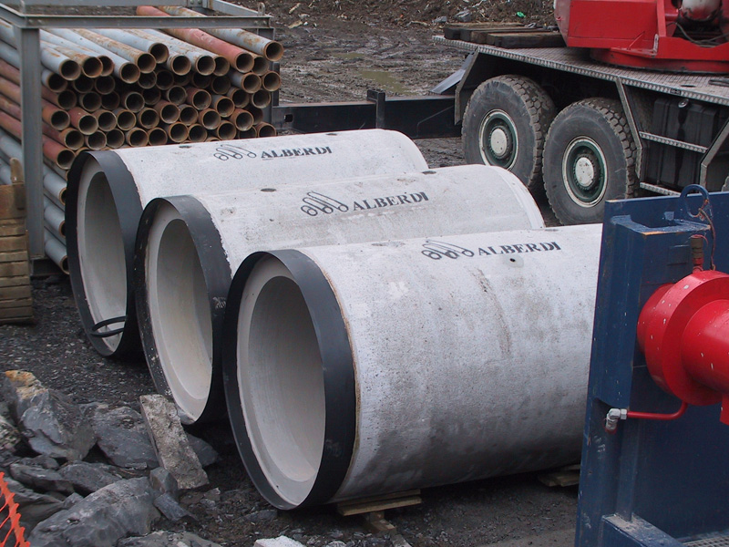
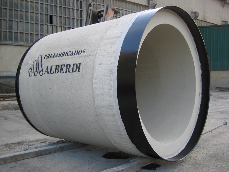
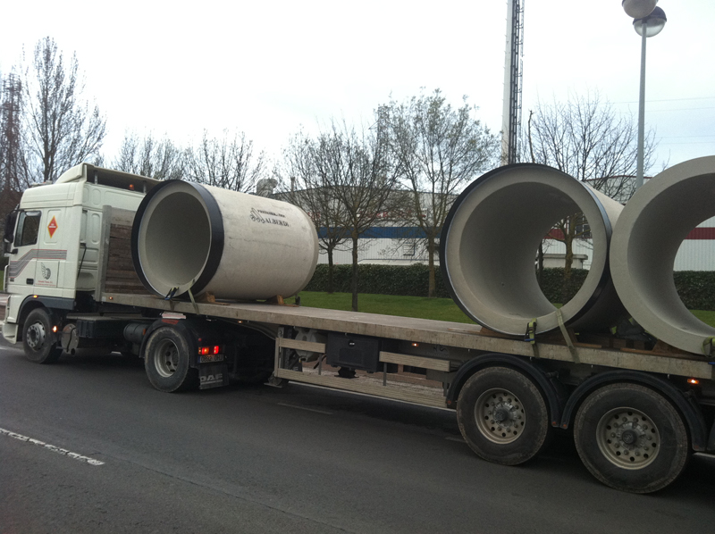
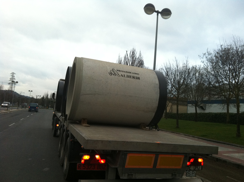
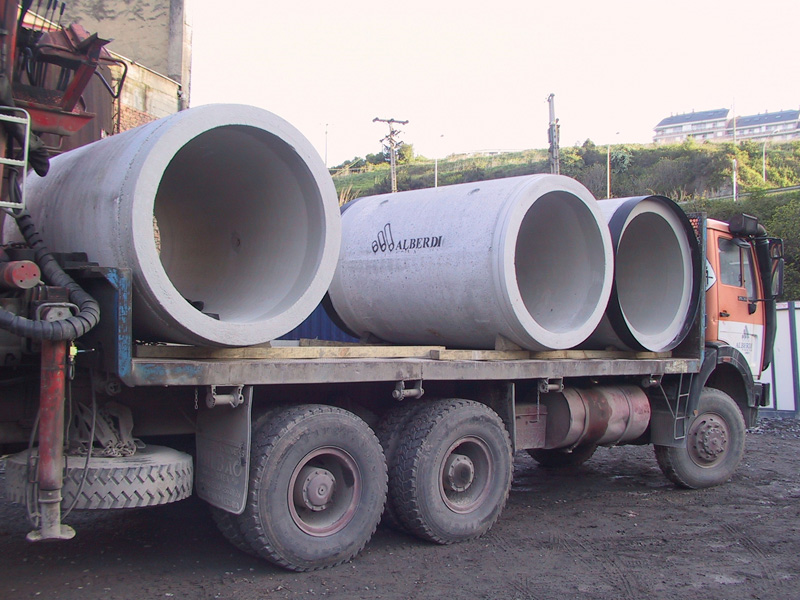
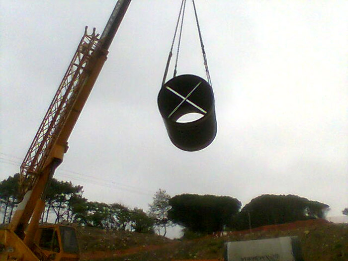
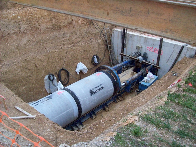 The reinforced concrete jacking pipes by Prefabricados Alberdi S.A. are pipes that are installed without the need to create an open trench. Reinforced concrete jacking pipes are mainly used for black water, rainwater and surface water using gravity or, occasionally, low pressure.
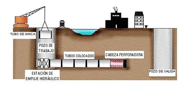
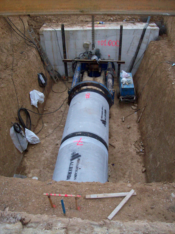
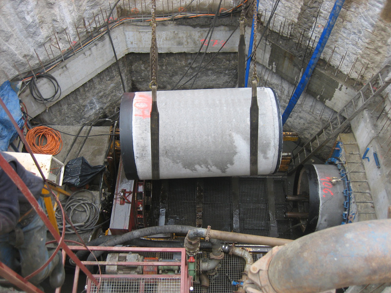
This is why reinforced concrete jacking pipes are a clear alternative in extraordinary situations or when there are execution problems, such as:
- The need to pass under motorways, railways or existing buildings.
- Crossing rivers or areas where the water table is very high.
- In projects where the depth of the trench is excessive. From 8m deep and 50m long, jacking pipes are considered a real, very economical alternative to pipes in trenches.
- Renewal of wastewater networks in urban areas.
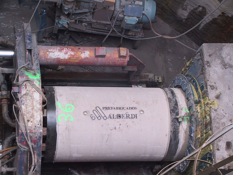
Jacking pipes can be manufactured using the radial compression or vibrocompression methods.
At the same time, the European Directive 89/106/CE of Royal Decree 1630/1192 establishes that reinforced concrete jacking pipes must have the CE marking complying with the provisions of the current standard in force, UNE EN 1916:2003. This is why at PREFABRICADOS ALBERDI S.A. we mark all our pipes accordingly.
For special applications for outfalls, contact us
SPECIAL APPLICATIONS FOR CONCRETE JACKING PIPES
PREFABRICADOS ALBERDI, S.A. has all types of technical solutions to face any type of challenge that may arise during the execution of projects involving jacking pipes, such as curved piping, ocean outfalls, etc.…
In the case of jacking pipes for curves, the thrust is calculated depending on whether the joints are closed or open. Using the criteria of the German standard ATV 161, in this type of special application the following factors that affect the determination of the thrust force permitted for the jacking pipes will be redesigned:
- The geometry of the pipes, emphasizing the useful length to obtain a lower permitted turn radius.
- The design of the collars, analysing the need for longer collars.
- The geometry of the thrust transfer rings or braces, and the properties of the materials used in these braces (behaviour of the material against the stresses, especially with repeated loads and their compressibility).
Continuing with the special applications, PREFABRICADOS ALBERDI, S.A. is also able to make ocean outfalls and projects with a high water table. This type of projects would need special technical solutions such as:
- The use of double or triple sealing gaskets. In this case, and using the compressibility of the brace, block or igloo type gaskets can be used in both the inner and outer diameters of the brace, in such a way that upon commissioning, the very compression generated by the pushing force on the brace commissions these rubber gaskets.


- Bentonite injectors with non-return valves. When fitting or removing the bentonite lubrication hoses in the injector, non-return valves may be used to keep water out and obtain greater quality in the execution.
TECHNICAL DATA
VIDEO
COMPONENTS
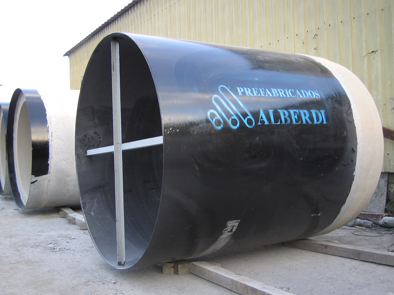
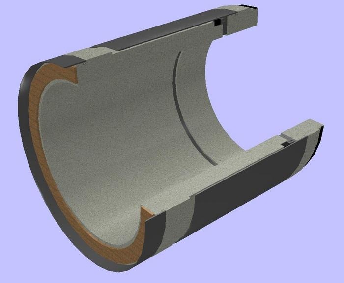
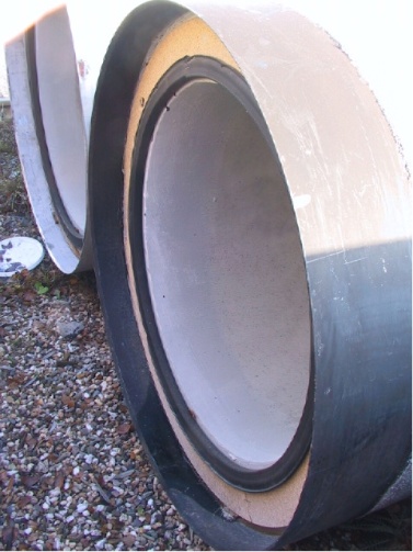
Jacking pipes consist of various characteristics that distinguish them from pipes in normal trenches, such as:
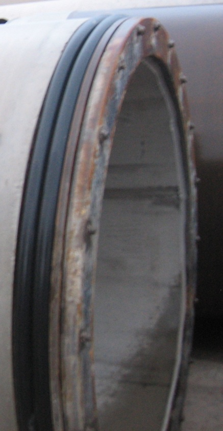
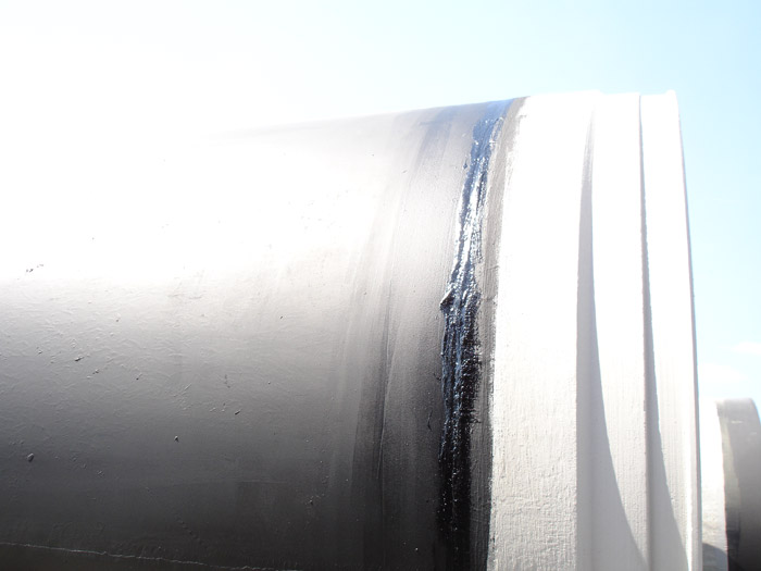
- Collar: metal ring made of weldable, hot-dip galvanised steel that is then painted with coal tar epoxy to delay the chemical corrosion of the steel. The principal function of this element, rigidly connected to the concrete, is to achieve a full seal along the whole pipe using separate elastomeric gasket. In addition, they allow possible intentional and unintentional rotations and curves to be absorbed during the jacking, avoiding possible leakage this could cause.
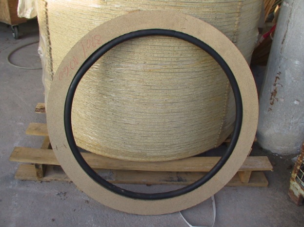
- Brace: wooden ring placed between the different thrust surfaces of two consecutive pipes. Its principal function is to absorb the possible irregularities of the connection or if the faces are not perpendicular so that stresses are not concentrated in the concrete during jacking.
- Bentonite injectors: three galvanised metal threads embedded in the wall of the pipes, spaced at 120º, are used to inject bentonite slurry from the interior of the pipe into the cavity between the soil and the pipe. This slurry has two main functions: to reduce the friction between the soil and the pipe being jacked; and prevent the tunnel made by the boring machine crumbling when the pipes are jacked.
NOMINAL DIMENSIONS
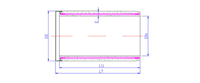
| DN (mm) | DE (mm) | E (mm) | LU (mm) | THRUST (KN) | WEIGHT (kg/ml) |
|---|---|---|---|---|---|
| 300 | 550 | 125 | 2,000 - 2,400 | * | 420 |
| 400 | 660 | 130 | 2,000 - 2,400 | * | 545 |
| 500 | 760 | 130 | 2,000 - 2,400 | * | 650 |
| 600 | 860 | 130 | 2,000 - 2,400 | * | 750 |
| 700 | 960 | 130 | 2,000 - 2,400 | * | 850 |
| 800 | 1,100 | 150 | 2,000 - 2,400 | * | 1,075 |
| 1,000 | 1,280 | 140 | 2,400 | * | 1,280 |
| 1,200 | 1,490 | 145 | 2,400 | * | 1,585 |
| 1,200 | 1,500 | 150 | 2,400 | * | 1,625 |
| 1,200 | 1,500 | 150 | 3,000 | * | 1,625 |
| 1,400 | 1,740 | 170 | 2,400 | * | 1,785 |
| 1,500 | 1,860 | 180 | 2,400 | * | 2,415 |
| 1,600 | 1,940 | 170 | 2,400 | * | 2,395 |
| 1,800 | 1,860 | 195 | 2,400 | * | 3,080 |
| 2,000 | 2,400 | 200 | 2,400 | * | 3,475 |
| 2,500 | 3,000 | 250 | 2,400 | * | 5,350 |
* The calculation of the maximum thrust force the pipes can bear depends on the type of project and if the jacking is straight or curved. For this purpose a more exhaustive, more specific analysis of the jacking method will be necessary.
NAME AND REGULATIONS FOR CONCRETE JACKING PIPES
RESISTANCE CLASS
Ff: Cracking load (KN/m2)
Fn: Breaking load (KN/m2)
ACCORDING TO UNE EN 1916
| CLASS 60 | CLASS 90 | CLASS 135 | CLASS 180 | |
|---|---|---|---|---|
| Ff | 40 | 60 | 90 | 120 |
| Fn | 60 | 90 | 135 | 180 |
ACCORDING TO ASTM C76 M
| CLASS I | CLASS II | CLASS III | CLASS IV | CLASS V | |
|---|---|---|---|---|---|
| Ff | 40 | 50 | 65 | 100 | 140 |
| Fn | 60 | 75 | 100 | 150 | 175 |
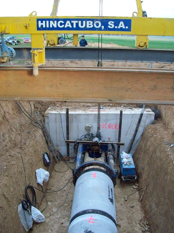
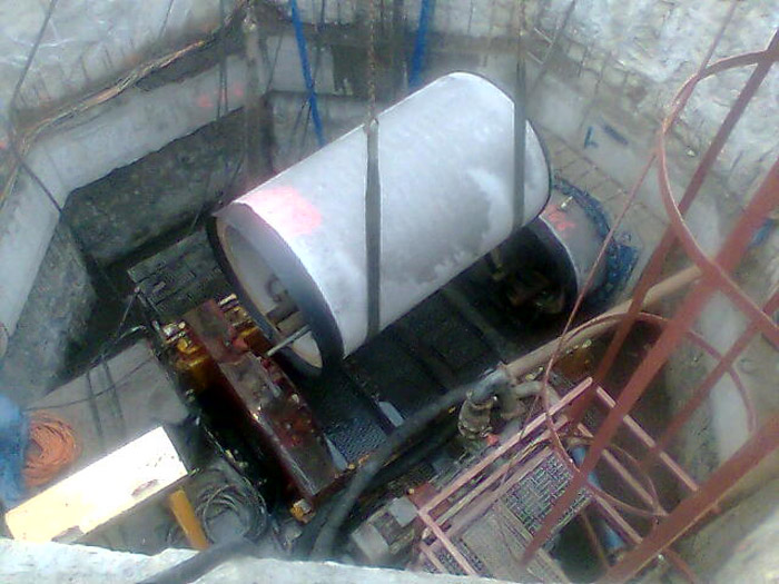
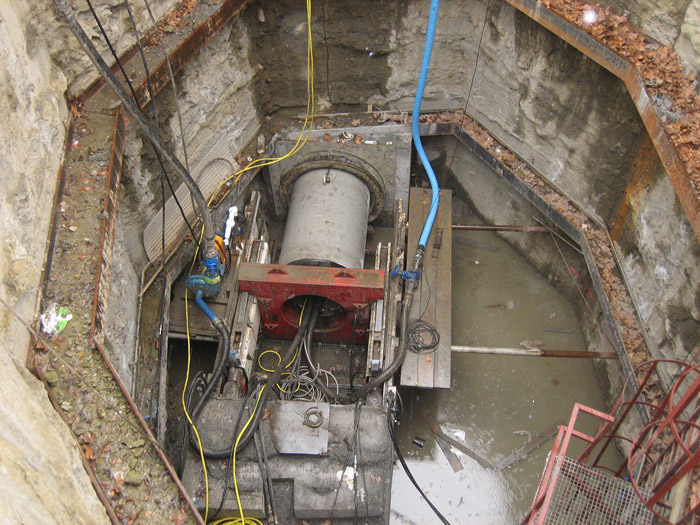
Jacking shields
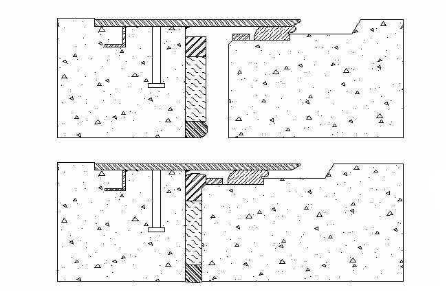
The jacking shields are secondary thrust elements whose principal function is to prevent the maximum thrust force of the pipes being exceeded during jacking.
The function of the shields is to mimic the movement of a caterpillar; the principal thrust shield situated in the drive pit will move the pipe to the first intermediate shield, which will retract and, once the principal one is established, it is activated so that the line in front of it is moved forward. Combining these movements of thrust between the principal shield and the different intermediate shields makes the jacking progress to the reception pit.

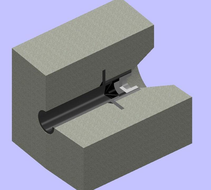
Habitually, the intermediate shields are placed between 25 and 50m behind the tunnelling or boring machine, and then approximately every 100m or 150m, depending on the specifications of the project.
The intermediate shields by PREFABRICADOS ALBERDI, S.A. are always manufactured with the shield firmly secured to the screw tap and both the screw tap-shield and the recessed pipe are fitted with thrust discs, ensuring a better distribution of the thrust.
The gasket of the intermediate shields always works with the support base and steel contact surface to ensure greater tightness during the jacking process and in the movements typical of the functioning of the intermediate shields.
 In the case of special applications, PREFABRICADOS ALBERDI, S.A. will design the intermediate shields depending on the needs of the client and the project. Intermediate shields can be manufactured with Bentonite injectors in the rubber gasket for sandy earth or intermediate shields with active gaskets for special applications such as terrains with a high water table or ocean outfalls.
This system is based on the fact that the sealing gasket can be compressed by a system of screws depending on whether there is a waterway or bentonite due to an increase in pressure or the very deterioration of the rubber gasket, thus adjusting the compression of the gasket at all times during the jacking process.
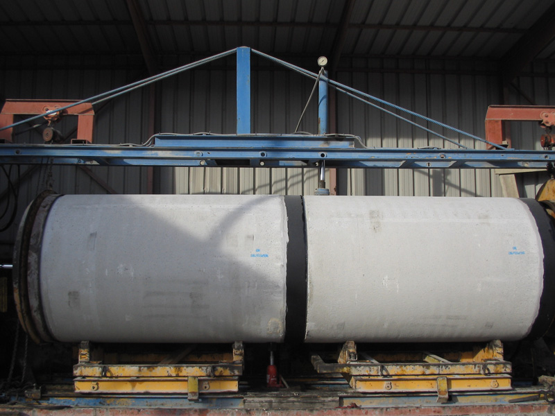
QUALITY CONTROL
The following quality controls shall be made:
- Compression resistance of specimens of fresh concrete
- Analysis of the consistency of fresh concrete
- Layout of reinforced elements
- Mechanical resistance: breakage test of three edges according to ASTM-C497M, pt.4
- Alkalinity and water absorption
- Tightness tests on the gasket according to BRITISH STANDARD 5911, Appendix H (up to Ø1,200 included)
- Hydrostatic tests according to BRITISH STANDARD 5911, Appendix H (up to Ø1,200 included)
At the end of all these product verifications, a technical dossier will be submitted with all the results of the tests and analyses carried out on both the pipes and the starting materials used.
PHOTO GALLERY


We use our own and third party cookies, for the analysis of user navigation. If you continue browsing, we consider that you accept the use.
You can change the settings or get more information here.

Arriandi auzoa, 1
48215 Iurreta (Bizkaia)
Tel.: +34 94... see telephone number
Fax: +34 94... see fax
Prefabricados Alberdi - Copyright 2012 | Legal notice | Data protection | Sitemap | Cookies


Website site designed 
and developed by DMacroweb